
Updated:
29.06.2020


|
|
Single Stretched Vibrating Wire (VW) Measurement System
The description below is work in progress (July 2018, updated after lab move Feb 2020, June 2020).
The single stretched vibrating wire (VW) system is well suited for the determination of the magnetic axis of
quadrupole magnets. VW was extended to be used with sextupoles and also to skew magnets.
The method was generalised for multipoles, normal or skew and can be applied for any such
magnet type if needed.
The axis information has often to be expressed in a coordinate system including reference points mounted on the magnet, needed
when the magnet is mounted in the accelerator. For Swiss FEL quadrupoles, a survey instrument mounted on the table of the VW set-up was used.
Other referencing schemes can be envisaged.
As of writing, the entire system uses no less than 3 different operating systems, 5 computers and leverages on EPICS.
Interoperability is provided by several Phyton scripts running on Linux. .
Survey and working coordinate system:
- Place the appropriate magnet support (QFM, QFF, etc) on the table
(approximately a quarter wire length from the stages pair 1)
- Using a survey instrument (for example the FARO arm), define a working reference frame using the magnet holder, following if available,
the convention of the accelerator (Z+ // beam, x = y = 0 for a beam on axis.
- Adjust the position of the wire holders WH1 and WH2 so as to position the mounted wire center along the Z axis.
The reference points of the wire HOLDERS are offset from the wire mounting points by an amount determined in a separate calibration.
These values are used as criteria to position the linear stages so as to place the wire CENTER on the nominal Z axis at X = Y = 0, in the working reference system.
The situation is sketched here. One needs to adjust the internal coordinate values of each individual stage in the file ../cmd/mylib_utils.py.
Example: the X offset of WH1 is 17.02 mm. Thus, a stage position recorded by the survey instrument reads X = -17.02 mm - (wire thickness/2) when the wire center is on axis at X =0.
The shift due to the wire thickness/2 can also be ignored and corrected later using the script magax_res.py. The whole adjustment procedure can be lengthy and is temperature dependent.
- The table on which the experiment is mounted provides two reference points P13 and P14, useful to track unwanted shift and/or rotation of the working
reference system. The impact of a severe temperature change can also be registered.
- Executing the script goHome.py reads the position of the WH1 and WH2 stages from the mylib_utils.py file and moves them
to their internal value; this position becomes the status of a HOME = X = Y = 0.
- Subsequent magnetic axis determination using the script magax.py will express DIFFERENCES relative to that home,
using the internal encoders of the stages. An additional geometrical survey of the position of WH1 and WH2 allows to express the position of the wire
in a coordinate system including the reference points of the magnet.
- In a perfect world, the axis position expressed as difference by the encoders of the stages should be identical to the differences registered by the survey instrument.
The script magaxFARO.py attempts this comparison by reading the survey data previously stored on an appropriate /afs volume and the data generated by magax.py.
- It is good practice to track, with the survey instrument, the actual home values of WH1 and WH2 before and after a axis determination.
VW-table setup:
- place the magnet on its support
(approximately a quarter wire length from the stages 1)
- stretch and fix the wire through the detector (CROC) and through the magnet
- ensure that the wire holders' electrical contacts are tightened
- ensure that the 4 linear stages are each connected to their drivers SMC100/li>
- if necessary position two (of 4) temperature sensors onto the magnet
- if necessary add one (of 4) temperature sensor on the water cooling line of the magnet
- if necessary add one (of 4) temperature sensor measuring air temperature in the hutch
- connect electromagnets to a suitable power supply
- if necessary connect cooling water lines to the magnet (verify for leaks)
- switch off the light and close the door before the measurement starts
Instruments connection setup:
- connect the constant current source (CCS) with the cables from the wire holders
- connect the ZI HF2LI Signal Output 1 with the constant current source
(put a current measurement device in series, like Fluke 8846A)
- connect the ZI HF2LI Signal Input 1 and 2 with the detector
(cables marked with XR and XL to channel 1, YB and YT to channel 2)
- connect the ZI HF2LI with the USB cable to the Mac mpc1320
(the Mac must also be connected to the network)
- ensure that the stages are connected to the SMC 100 motion controllers
- connect the SMC 100 motion controllers to the the serial port of MMM-PC-MMM
(must also be connected to the network)
- ensure that the temperature sensors are connected to their controller unit
(must also be connected to the network)
Software controls and utilities:
This assume computers pc7455, headless MMM-PC-MMM and headless MMM-PC-MMN are up and running on the network.
- log in to the Magnet Section account on the Mac mpc1320
- start XQuartz and ssh log in to your account on pc7455 with PSI credentials
- start the VMware Fusion / virtual SL6 machine on mpc1320 and log in with PSI credentials
- run /usr/bin/ziServer --port 8005 --debug 7 --open-override 1 telnet localhost 8005& on virtual SL6 running on mpc1320
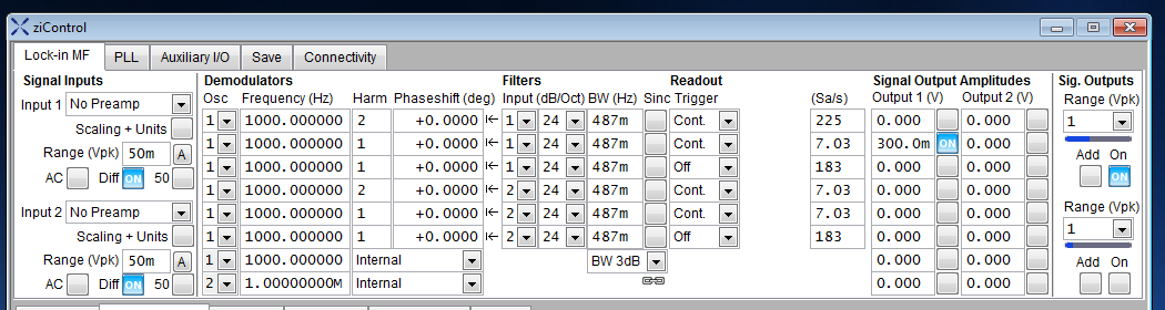
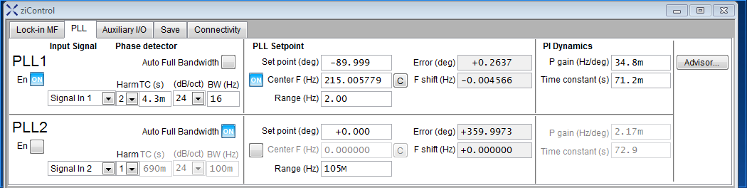
- run the /usr/bin/ziControl& on virtual SL6 and adjust settings of the lock-in as illustrated in
MF tab and PLL tab. (may need to temporarily unplug all USB devices and plug only the ZI HF2LI)
- (same tasks can be performed by running ziControl and a ziServer on virtual Win7 machine. For this USB connected to mpc1320 must be re-rooted to virtual Win7. GUI of on Win7 ziControl is of slight better graphical quality).
- after turning on the Signal Output check the current through the wire
(the best value depends on the vibrations, do not exceed 1 mV in the vibration signal)
- Temporary solution: connect the power supply (PS) to the magnet. Currently, PS control can be achieved with pc12595 of the rot coil rig.
- If the LEDs on the SMC 100 linear stage driver units are not green, run the command NOT_REFtoREADY on pc7455
(follow the command with the stage name parameter 1H, 1V, 2H and 2V)
- Temperature and humidity control
- run goHome.py on pc7455 to check the HOME position and instruments connections
(see Survey and working coordinate system)
- run scanFreq.py on pc7455 to find and adjust the wire resonance frequency
- run magax.py on pc7455 to execute a series of measurements
- complete the measurement with magaxFARO.py on pc7455
Run it and perform survey immediately after the magnetic axis has been found. This script requires access to the survey data (/afs/ ... .csv file)
of the references points of WH1,2, the magnet, and the VW table P13 and P14. (The script is sensitive to the
format of the output of each point. CAM 10 SW exports data with two flavours. Edit the .csv file if necessary or find a workaround
to force CAM 10 to export all points using the same flavour.) It reads magnetic and survey data and and computes the difference between stages positions measured
by the internal encoders and the survey method.
- run magax_res.py on pc7455. This script reads all the available data in a given folder and writes an overview on the screen; no new file is written.
Further, this script corrects for the wire diameter only on data sets identified in a list that needs to be edited in magax_res.py. The required information is taken from
the home values of WH1 and WH2 edited in mylib_utils.py .
Here is the magax.py header with some useful information bits.
 //======================================================================================\\
 ||                                                                                      ||
 ||     This is a python script:                                                         ||
 ||                                                                                      ||
 ||        magax.py  (version :  3.1.8, from 15-Jul-2015 15:27)                          ||
 ||                  (author  : V. Vrankovic)                                            ||
 ||                                                                                      ||
 |>======================================================================================<|
 ||                                                                                      ||
 ||     It will find magnetic-to-geometric axis offset for most multipole magnets.       ||
 ||     It will also calculate the roll angles of all cross-section symmetry lines.      ||
 ||                                                                                      ||
 ||                                                                                      ||
 ||     Usage:                                                                           ||
 ||        magax.py  nRuns, dir, operator, magName, magType, curr, freq, "comment"       ||
 ||                  nRuns   ==> < 0  for a run without graphics                         ||
 ||                  dir     ==> "."  for the current directory                          ||
 ||                  magType ==>  "q" for quadrupoles                                    ||
 ||                              "sq" for skew quadrupoles                               ||
 ||                               "h" for sextupoles                                     ||
 ||                              "sh" for skew sextupoles                                ||
 ||                                                                                      ||
 ||                                                                                      ||
 ||     -> ensure that the Zurich Instruments HF2LI Lock-in Amplifier is linked          ||
 ||        with the vibrating wire setup, is turned on and connected with a USB          ||
 ||        cable to the Mac mini mpc1320 running Linux virtual machine vmpc1320          ||
 ||            /usr/bin/ziServer --port 8005 --debug 7 --open-override 1                 ||
 ||            telnet localhost 8005                                                     ||
 ||                                                                                      ||
 ||     -> EPICS servers:                                                                ||
 ||        pc7455     : Zurich Instruments HF2LI lock-in amplifier                       ||
 ||        mmm-pc-mmm : Newport M-ILS150CCL stages                                       ||
 ||        mmm-pc-mmn : Sensirion SHT75 temperature sensors                              ||
 ||            service shellbox status 50001                                             ||
 ||            sudo service shellbox restart 50001                                       ||
 ||                                                                                      ||
 ||     -> HF2LI settings:                                                               ||
 ||            TC=140ms, 24dB/Oct, 7.03Sa/s                                              ||
 ||            Input 1                   Input 2                                         ||
 ||            DEMOD-1(2w):vibX          DEMOD-4(2w):vibY                                ||
 ||            DEMOD-2(1w):posX          DEMOD-5(1w):posY                                ||
 ||            Output 1, Demod-2, 296.1mV --> 50mA                                       ||
 ||            PLL-1, Harm=2, TC=4.3ms, 24db/Oct                                         ||
 ||            PL Dynamics, gain=34.76m, TC=71.2m                                        ||
 ||                                                                                      ||
 \\======================================================================================//
|
|
